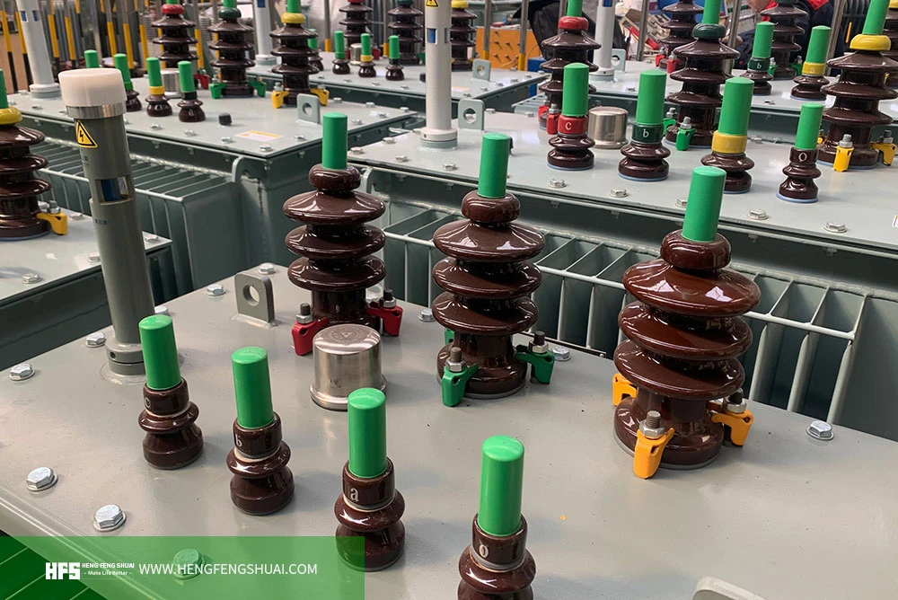
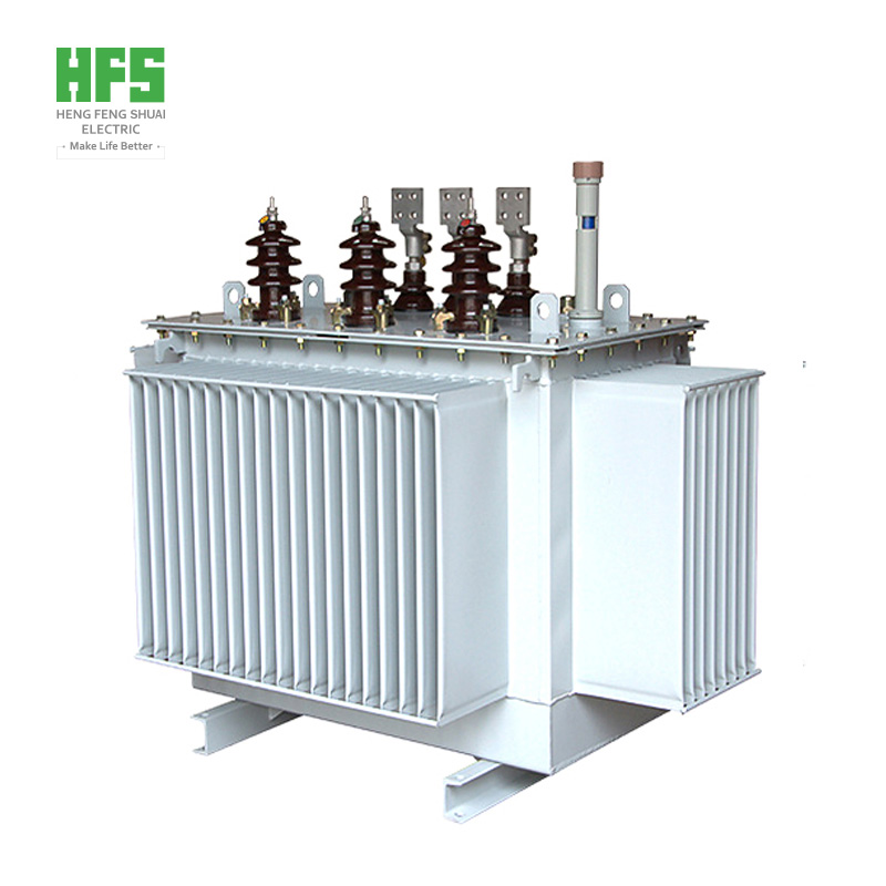
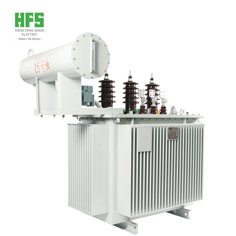
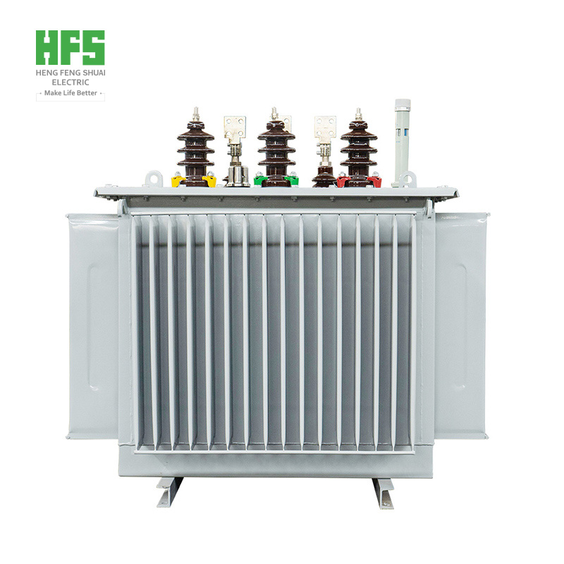
A transformer is a static motor, which is used to transfer alternating current from one circuit to another at a stable frequency through electromagnetic induction. However, the voltage will increase or decrease as needed, mainly for increasing or decreasing the voltage in the circuit.
It is understood that each transformer includes different components, such as iron core, winding, coil, insulating material, oil conservator, oil, vent, tap changer, Buchholz relay, cooling pipe and explosion-proof door. The winding of the transformer plays a key role in operation. Therefore, this paper briefly introduces the types, functions and application characteristics of lower transformer windings.
Concept of transformer winding
The transformer winding comprises copper coil bundles with different turns, wherein each bundle is connected to form a winding. The winding mainly depends on the input and output power supply, otherwise it depends on the voltage range. The winding diagram of the transformer is as follows:
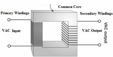
There are two types of transformer windings: primary winding and secondary winding. Its working process is that the primary winding receives power from the power source, and the secondary winding transmits power to the load.
In addition, the transformer winding materials are aluminum and copper, which are the most commonly used conductors in the transformer winding. Copper has high mechanical strength and electrical conductivity, while aluminum has lower cost and lighter weight than copper. In general, copper windings are used for large transformers, while aluminum conductors are used for small and medium transformers.
Transformer winding type
Transformer windings have the following different types, mainly including the following categories:
Multilayer spiral winding
Spiral winding or spiral winding
Disc winding
Foil winding
Cylindrical winding
Cross winding
Disc and continuous disc windings
Aluminum winding
1. Multilayer spiral winding
Multilayer spiral winding is mainly used for high-voltage transformers based on rated voltage, such as 110kV and above. These types of windings include many cylindrical layers wound and connected in series. The outer layers of these transformer windings are shorter than the inner layers in order to uniformly distribute the capacitance. These windings are mainly used to enhance the surge behavior of the transformer.

2. Spiral winding or spiral winding
Spiral winding is called spiral winding, which is used in low-voltage and high-capacity transformers, where the current is high and the number of winding turns is small. The transformer outputs from 160 to 1000 KVA and 0.23 to 15 kV.
In order to protect sufficient mechanical power, its cross-sectional area is not less than 75mm to 100mm square, and the maximum number of strips used to form parallel conductors is 16. These windings have three types: single helix, double helix and disk helix.
The winding along the thread in the axial direction by tilting is called a single helical winding. These windings contain only one layer of turns in each winding.
The double helix winding reduces the eddy current loss in the conductor. Therefore, since the number of parallel conductors is reduced, they are used in the radial direction.
The design method of the coil spiral winding group is that the strips are connected side by side in the radial mode to occupy the entire radial strength of the winding.
3. Disc winding
The design of disc winding can be completed by connecting several conductor discs in series. Initially, a disc can be formed by winding different insulated conductor turns, and then connecting them in series to make a disc winding. Each disc can be separated from the adjacent disc by a gasket.
The main difference between the disc winding and the spiral winding is that the spiral winding only includes a single twist of the parallel conductor of each disc, while the disc winding includes many turns of each disc. The rated transformer above 25kV adopts disc winding. Like the spiral, these windings are mechanically strong.
4. Foil winding
The foil winding is mainly designed with thin aluminum or copper sheet, and the thin insulating sheet is covered for several times to make multi-layer spiral winding. The winding may be formed by a single piece or a plurality of pieces wound in parallel on the plane side. These are suitable for large capacity transformers with a current range of 12 – 600A.
5. Cylindrical winding
These windings use a low voltage of up to 6.6kV with a rated current range of 10 – 600A. These windings are often used in multi-layer form. In these types of windings, circular conductors wound on vertical bars can be used to enhance the cooling conditions. This arrangement will form an oil passage to help better cooling. Cylindrical windings are suitable for high voltage ratings up to 33kV, 800kVA and up to 80A rated current. For bare conductors, the maximum diameter used is 4 mm.
6. Cross winding
Cross windings are used in small transformers. These windings are divided into several coils to reduce the voltage between adjacent layers. These coils are separated by a distance of 0.5 to 1 mm in the axial direction. The voltage between adjacent coils shall not be higher than 800 – 1000V. The actual axial length of each coil is about 50 mm, and the spacing between the two coils is 6 mm to accommodate the block of insulating material. The width of the coil ranges from 25 mm to 50 mm. Under normal conditions, these windings have higher strength than cylindrical windings.
7. Disc and continuous disc windings
This type of winding is generally used in transformers based on high capacity, where these windings include a plurality of disk or flat coils configured in series or parallel. These coils may be formed using rectangular strips spirally wound in the radial direction. The conductors in these types of windings are single or multiple strips in a parallel configuration wound on the horizontal side. The formation of this conductor will make the structure very strong.
In addition, the disks in these windings are separated from each other by pressing plate sectors, where these sectors are connected to vertical stripes. The conductor area is 4 to 50 mm2 and the current range is 12 to 600 a. The minimum width of transformer oil passage is 6mm, mainly used for 35kV. The main advantage of these types of windings is that they provide maximum mechanical axial strength.
8. Aluminum winding
Aluminum winding is the main choice for different transformers (such as dry-type and low-voltage) in North America. In most parts of the world, copper winding is the main winding material, but the main reason for choosing this kind of aluminum winding is its low initial cost. Compared with copper, aluminum winding is more flexible, so it is very easy to use. The maximum resistivity of aluminum provides less eddy current loss in the winding, which reduces the possibility of hot spots. Transformers with aluminum windings or copper windings have the same loss and performance. But the aluminum coil is larger than the copper coil.
HENGFENGSHUAI ELECTRIC, is an electrical enterprise with transmission and distribution industry as its main business, integrating product research and development, manufacturing and trade. Designated suppliers for the world's top 500 enterprises .Its main products include power transformers, medium and low voltage switchgear, distribution panel ,circuit breakers, transmission tower ,Cable and other power distribution equipment .The group has five department: Transformer department, Panel department, power transmission tower department, cable department and electrical engineering department. HENGFENGSHUAI ELECTRIC, has been working hard to provide the best transmission, distribution solutions for users all over the world.【WhatsApp:+86158 5325 2696(Jack) +86158 5326 5269(Alisa)hfs@hengfengshuai.com https://www.hengfengshuai.com 】
